by  ZOU
ZOU
Surface Mount Technology (SMT), commonly known as electrical equipment, refers to the circuit assembly technology on a printed circuit board that does not require a through hole to directly attach and solder surface mount components to a specified position on the surface of the PCB (ie, the pad).
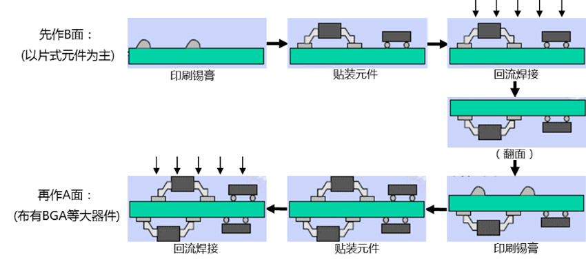
Our board electrical installation adopts double-sided reflow soldering process. The main process flow is as follows:
According to statistics, the top three in the industry are weak soldering, bridging, and less tin, and the occurrence of these undesirable phenomena is largely related to the setting of solder paste printing and reflow soldering temperature. Other defects such as sideways, tombstoning, shifting, reversing, and missing stickers are related to the patch.
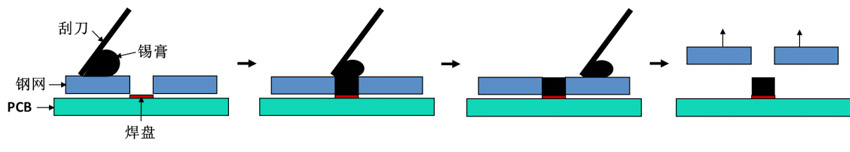
According to statistics, under the premise of correct design, quality of components and PCBs, 70% of the quality problems of electrical equipment are caused by solder paste printing. The quality of solder paste printing is mainly related to the following aspects:
1, solder paste quality: solder paste viscosity, printability, service life at room temperature, etc. will affect the quality of printing. The characteristics of the solder paste are related to the alloy composition, the metal content, the diameter of the tin powder, the type of solder paste, and the like;
2, stencil design: stencil printing is contact printing, so the thickness of the stencil and the size of the opening determine the amount of solder paste. Excessive amount of solder paste will cause bridging, and too little solder paste will produce solder or less tin. The shape of the stencil opening and whether the opening is smooth will also affect the transfer rate of the solder paste. In order to achieve the best solder paste release, the ratio of window opening area to sidewall area of the steel mesh should be greater than 0.66, which is an empirical value for achieving more than 70% solder paste transfer, and is also the basis for steel mesh design;
3, printing process parameters: mainly include scraper speed, scraper pressure, the angle of the scraper and steel mesh, PCB support and off-speed, etc., only to properly control these parameters, to ensure the quality of solder paste printing.
The defects of the patch mainly include side standing, tombstoning, shifting, reverse, and leaking. The three elements to ensure the quality of the patch are: correct components, accurate position, and appropriate pressure.
1. The components are correct: the type, model, nominal value and polarity of each component of the assembly number are required to meet the assembly drawing and schedule requirements of the product;
2, the position is accurate: the end or pin of the component should be aligned and centered with the land pattern as much as possible, and also ensure that the soldered end of the component contacts the solder paste pattern;
3. The pressure is suitable: the pressure of the chip is too small, the soldering end or the lead of the component floats on the surface of the solder paste, and the displacement is easy to occur during the transfer and reflow soldering; the pressure of the patch is too large, and the solder paste is excessively extruded, which easily causes tin The paste sticks and creates a bridge. At the same time, due to the sliding, the component position is shifted, and in serious cases, the components are damaged.
The essence of reflow soldering is “heating”, and the core of the process is the setting of the speed and reflow profile of the conveyor belt. The speed of the conveyor belt determines the heating time per zone. The reflow profile can be divided into four zones according to function, namely preheat zone, active zone, recirculation zone and cooling zone. Each zone can be divided into multiple temperature zones to make the real temperature as close as possible to the set temperature. At present, ten temperature zone reflow ovens are often used.
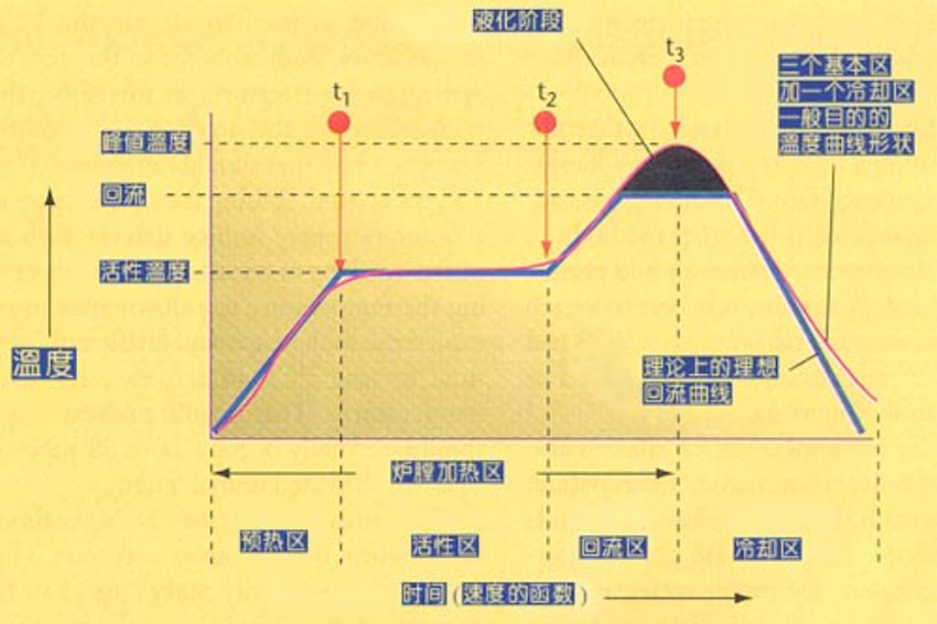
1. Preheating zone: Raise the temperature of the PCB to the required activation temperature. The preheating start temperature is usually about 50 ° C lower than the preheating end temperature, and the preheating end temperature is usually set to 20 to 30 ° C below the melting point of the solder paste;
2. Active zone: This zone has two functions: 1 to reduce the temperature difference between various parts of PCBA during welding; 2 to activate the flux, volatile substances such as solvents are volatilized from the solder paste. The holding time is generally 2~3min, as long as the PCBA reaches the basic heat balance before entering the reflow soldering stage. Under this premise, the shorter the better. From experience, as long as the holding time is less than 5 minutes, there is generally no so-called flux premature failure problem;
3. Reflow zone: The area where the welding is actually performed. The principle of temperature design is that the peak soldering temperature of all components can not be higher than the highest heat-resistant temperature of the component, nor can it be lower than the minimum temperature requirement of the soldering. Under this premise, we hope that the lower the soldering temperature, the better. Generally, the peak temperature of the solder is set to be 11 to 12 ° C higher than the melting point of the solder paste and not higher than 260 ° C (lead-free process);
4, cooling zone: cooling is fast, the solder joint strength will be slightly larger, but too fast will cause temperature stress inside the component.
Because each step brings defects, in order to detect and eliminate defects, a product must undergo at least 5 inspections during the electrical installation process:
1. The first piece inspection: the first piece of placement is carried out before production, and the first piece inspection is OK before mass production;
2, printing quality inspection: inspection of the printing quality of solder paste, no leakage, offset, solder paste bridging;
3, patch quality inspection: inspection of the quality of the patch, there must be no side, monument, shift, reverse, missed stickers, etc., when the defect is found, timely correction;
4. AOI automatic optical inspection: The products finished by reflow soldering are tested by AOI optical contrast method. The AOI test must also be performed again after the defective product is repaired;
5. Sampling before shipment: According to the corresponding standard regulations, the product quality will be sampled.
Since the AOI inspection cannot observe the solder joint condition of the bottom pad, it is necessary to check the bottom pad solder joint in conjunction with the X-RAY device.